QUESTION IMAGE
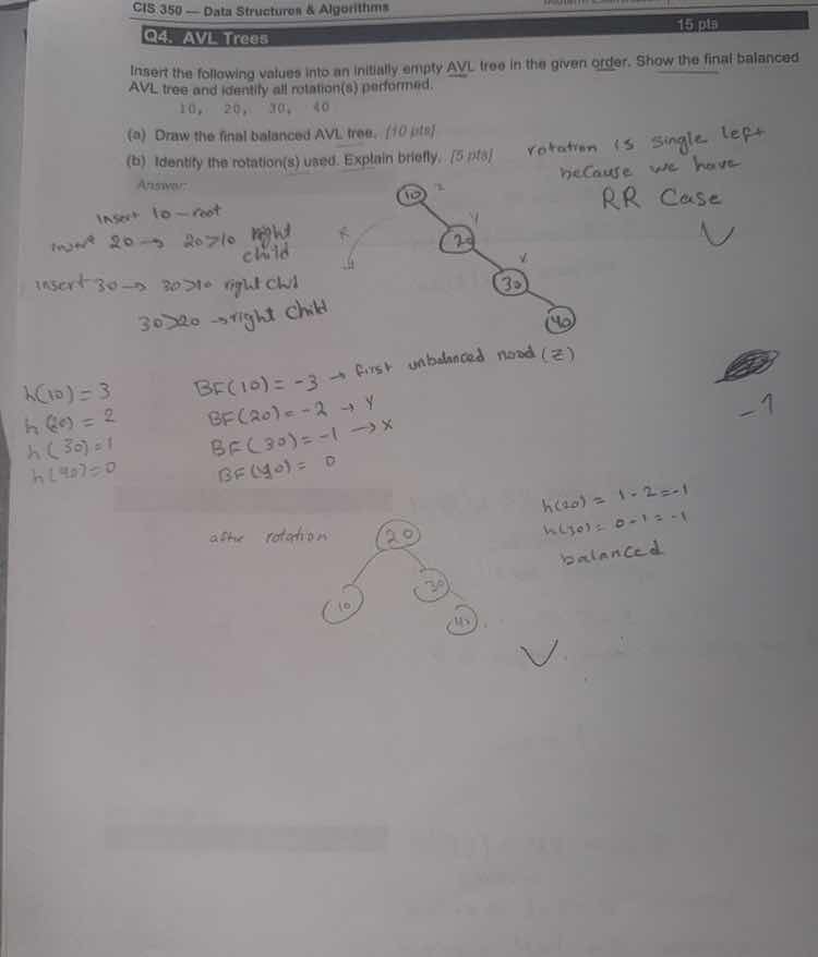
Question
cis 350 - data structures & algorithms
q4. avl trees
insert the following values into an initially empty avl tree in the given order. show the final balanced avl tree and identify all rotation(s) performed.
10, 20, 30, 40
(a) draw the final balanced avl tree. 10 pts
(b) identify the rotation(s) used. explain briefly. 5 pts
Insert 10, 20, and 30
Insert 10 as root.
Insert 20 as right child.
Insert 30 as right child of 20.
The tree is temporarily:
Calculate balance factors:
Node 10 is unbalanced (Right-Right case).
Perform Left Rotation on 10
Perform a single left rotation at node 10:
- Node 20 becomes the new root.
- Node 10 becomes the left child of 20.
- Node 30 remains the right child of 20.
The balanced tree is now:
Insert 40
Insert 40 as the right child of 30.
The tree structure becomes:
Check Balance Factors
Calculate balance factors for all nodes:
All balance factors are within \([-1, 1]\).
The tree is balanced.
Identify Rotations
A single left rotation at node 10 was performed.
This rotation resolved the Right-Right (RR) imbalance.
No further rotations were needed after inserting 40.

Snap & solve any problem in the app
Get step-by-step solutions on Sovi AI
Photo-based solutions with guided steps
Explore more problems and detailed explanations
Question (a)
The final balanced AVL tree is:
Question (b)
- Rotation Used: Single Left Rotation (also known as an RR Rotation) at node 10.
- Explanation: After inserting 10, 20, and 30, node 10 becomes unbalanced with a balance factor of \(-2\) due to a Right-Right (RR) path. A single left rotation at node 10 moves 20 to the root, with 10 as its left child and 30 as its right child. Subsequent insertion of 40 does not cause any further imbalance.